Required Parts:
- 4 x Flat Head Countersunk Screws (not included)
- DIN EN ISO 10642 – M6 Product Grade A – Property Class 8.8
Tightening Torque:
- Steel: 9.0Nm
- Aluminium: 6.0Nm
Installation:
Insert all 4 screws to the required torque (above) for the appropriate receiving material. The screws should be appropriate to ensure at least 10mm threaded insertion length into the wall.
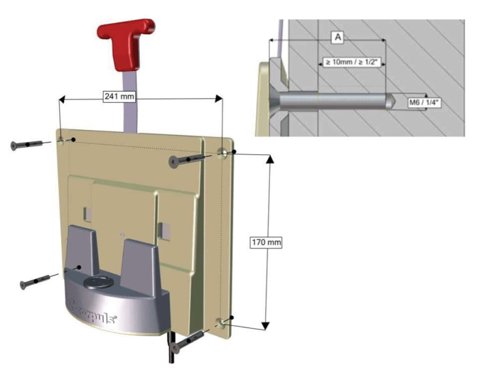
Figure 1: Installation Schematic of the Bracket
Electrical Connection:
The bracket supplies power to the Corpuls3 using a MagCode power port. When the unit is placed on the bracket, the port is pulled up to meet the defibrillator (using magnets fitted to the
Corpuls3 connector) and the internal switch is closed, making the contacts live. When no unit is installed on the bracket, the internal switch is open circuit, disconnecting the contacts and isolating them from the vehicle supply.
The charging bracket is supplied with a cable terminating in a DIN 4165 power plug. This should be plugged in to an appropriate socket near the mounting area. The cable should be run in a tidy manner and secured so as not to impede use of any items on the vehicle.
If the DIN plug is to be removed and the wired directly to a power feed, maintain the polarity of the original plug.
- Yellow & White – 12V Positive (Both wires should be connected)
- Green & Brown – Earth (Both wires should be connected)
The charging bracket can supply up to 9A to the Corpuls3 during charging, therefore it is recommended that the supply be fused at 15A assuming no other loads share the same output.
Care should be taken when running the cable that it is not pulled tightly from the bracket or forced to bend too tightly from the strain relief gland. Excess tension could force movement inside the bracket preventing free movement of the MagCode port.
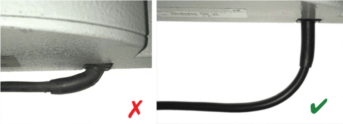
Figure 2: Wire and strain relief pulled too tightly (L). Proper cable run and bend radius (R)
Ensure that the DIN socket polarity is correct. Incorrect polarity may cause damage to the Corpuls3. A test plate can be supplied by Ortus Technology to facilitate testing the bracket before fitting a device.
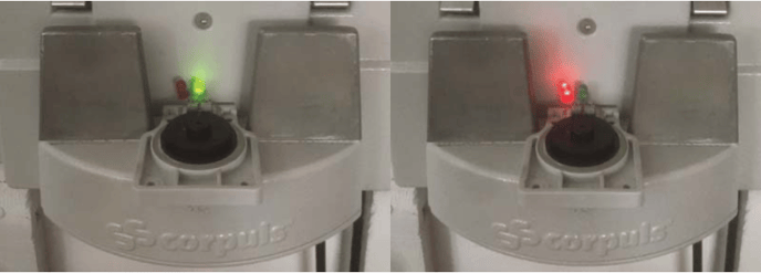
Figure 3: Left: Correct polarity (Green Light). Right: Incorrect polarity (Red Light)
Charging bracket and MagCode connector maintenance
If the two metal contacts in the contact field are oxidised or contaminated, clean the contact fields of the MagCode connectors (at the charging brackets, the AC adapter cable or at the DC connector cable) with a glass fibre brush pen.
Abrasive materials such as emery cloth should not be used as this can cause damage and wear to the contact pins